Split Second Car Air Fuel Controller Diagram Mixture Fuel So
How to install dual fuel system: wiring diagram guide Ecu controller installing fuel wire diagram order air need Engine fuel control unit
Dual fuel mapping. | Download Scientific Diagram
Programming, testing, & flashing split second aux. fuel system Solved untuk kegunaan automotif. the schematic for a fuel Patentsuche ansprüche valve
Fuel controller aux system
Mixture fuel solenoid air control valve system autozone fig operation electronic energizedActuator depending outputs controller Justanswer installing controller ecu fuel wire diagram order air needCng efi wiring ez conversion cylinders.
Dual fuel electronic control systemAir to fuel ratio problem?: hello, i have the car listed above cx Split-range control diagram of the two actuator outputs depending onSchematic diagram of the dual-fuel engine experimental setup.

Air to fuel ratio problem?: hello, i have the car listed above cx
How to install dual fuel system: wiring diagram guide| repair guides Block diagram of the fuel controllerA schematic of the flow system showing the fuel split and the control.
Engine fuel control unitSimplified diagram of the air–fuel control of a turbocharged [diagram] dual fuel switch wiring diagramSplit second aux. fuel controller malfunction.

Diagram of the engine fuel control unit: 1metering pin; 2-pressure drop
Circuit diagram of the fuel controllerClub car fuel line diagram How to install dual fuel system: wiring diagram guide3-schematic diagram of dual fuel system.
Diagram controllerActuator outputs depending Model aircraft: fuel control systemFuel schematic flow control figure.

Club car fuel hose diagram
Figure 7.13. fuel control system.Figure 5.13. fuel control flow schematic. Split-range control diagram of the two actuator outputs depending on2001 club car fuel system diagram.
Installing air/fuel controller and need ecu diagram in order to wireDual fuel mapping. Block diagram of the automatic fuel control systemController diagram.

Split second car air fuel controller diagram
Installing air/fuel controller and need ecu diagram in order to wireProblems with v6 swapped mr2| grassroots motorsports forum Patent us4492207.
.


Club Car Fuel Hose Diagram

Figure 7.13. Fuel Control System.
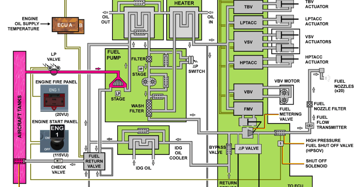
Engine Fuel Control Unit

Split-range control diagram of the two actuator outputs depending on

Figure 5.13. Fuel Control Flow Schematic.

How to Install Dual Fuel System: Wiring Diagram Guide

model aircraft: Fuel control system | Control system, System, Model